Land Rigs
Land Rigs are are relatively commoditised and the Chinese, Russians and Polish, amongst others, have been making very good ones for decades.
The ability to drill a hole down several thousand meters to test a potential reservoir is often taken for granted by non-oil industry observers and analysts. Indeed advances in the equipment used have improved the success rates in reaching targets, and perhaps even more importantly (but often under appreciated, even within the industry itself), the quality of hole drilled has improved. Higher quality well bores (straighter, less rugose) allow superior data to be acquired, and in a world where finding smaller reservoirs is the game, high quality data is paramount to understanding a reservoir, field and basin.
Up until the early 1900s well bores were ‘drilled’ by cable-drilling, which is still used for shallow water wells and foundation work on some building sites today. A cable pulls a heavy cylindrical weight up, and then simply lets it fall into the ground, and this slowly but surely makes the desired hole. Cable-drilling is only useful for very shallow wells, and by 1902 a new technique, rotary drilling, had been introduced in California.
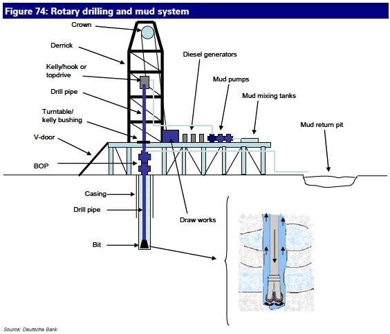
Rotary drilling is the technique used by oil rigs around the world today. A hollow pipe with a drilling bit on the end of it is rotated by one of two methods; either a ‘rotary table’ or a ‘topdrive’. The rotating bit cuts the rock beneath it, with the weight of the pipe pushing down on the bit carefully controlled, along with the speed of rotation, to ensure maximum cutting efficiency.
A fluid called ‘mud’ (which is actually a cocktail of expensive chemicals and custom designed for each section of each well) is pumped down through the middle of the drill pipe, comes out the drill bit and is circulated back up the annulus between the drill pipe and the hole. This performs several vital functions:
1) It carries away the cuttings from the drill bit
2) It provides lubrication to try and prevent the drilling pipe from getting stuck
3) It provides hydraulic pressure in the hole that prevents (in theory) any gas or oil from “blowing out”
4) It deposits a thin, impermeable layer of mud over the reservior zones called “mud cake”. This mud cake prevents further invasion and damage of the reservoir by drilling fluids and is vital from a data acquisition and productivity perspective.
Water Based Mud: A problem with water-based mud systems is that water is readily absorbed by clay. Clay beds (or ‘shale’) hence tend to swell when drilled through by water-based mud, and this swelling can cause no end of technical difficulties. Even if the driller can avoid the pipe getting stuck, he/she typically has to waste valuable drilling time going over the clay zones and back-reaming them to try and get rid of all the ‘sticky’ points. Not only that, but when the wireline logging operation commences (see later), swelled up clay zones are often the points at which wireline instruments become stuck, and to get them out again can take days of unproductive rig time.
Oil-base mud (OBM) uses oil rather than water as the solvent, and as such is not absorbed by clay. OBM usually results in better quality, faster drilled holes. The downside is 1) it is more expensive that water-based mud and 2) the returns from the well bore are full of OBM and hence care (i.e. expense) has to be taken to prevent any of this oil contaminated waste entering the local environment.
Rotary table and top drive. The method used to rotate the drill pipe nearly always takes one of two forms.
1) Rotary table, where a circular section of the drill floor rotates and via a ‘kelly bushing’ so causes the drill pipe to rotate, or;
2) Top drive, which is large electric or hydraulic motor which is positioned on top of the drill pipe.
The top drive, developed in the mid 1980s, was a big step forward in that it allowed more flexible drilling operations (mud can be pumped continuously no matter where the top of the pipe is in the derrick, whether back-reaming the drill bit up the hole or pulling the pipe out of hole – all of which are limited with a rotary table). The end result is fewer stuck pipes (and hence less lost wells), better hole quality (and hence better quality data from wireline logging) and better control when drilling deviated wells to target reservoirs.
Down hole mud motors. For directional drilling (in which a well is guided, sometimes at a high angle, to a very specific target) another option exists; instead of rotating the entire pipe, a hydraulic motor just above the drill bit is powered by the pressure and flow of mud being pumped through the pipe, and this motor provides the power to rotate the bit. This setup makes it easier to ‘steer’ the drill bit.
The BHA stands for ‘bottom-hole-assembly’. This refers to the bottom few hundred feet of the drill pipe and its basic form is usually made up by the drill bit followed by heavy pipe called ‘collars’ interspersed with larger diameter pipe with what look like fins on the side – so called ‘stabilisers’. The BHA assembly provides weight for the bit to cut rock, rigidity to keep the hole as straight as possible and strength to transmit torque to the bit and absorb huge mechanical shocks as drilling progresses.
The BHA can include several optional elements that make it more complicated – mud motors for directional drilling (as discussed briefly above). MWD (measurement-whilst-drilling) sensors to provide real-time direction and torque measurements or even LWD (loggingwhilst- drilling) instruments that can record various physical properties of the formation drilled through.
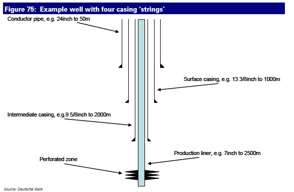
Casings. Wells are nearly always drilled in stages, and when the bottom of each stage is reached the freshly drilled hole, known as ‘open-hole’, is cased off using steel pipe and so becomes ‘cased-hole’. The main reason is to prevent the hole collapsing on top of the drill pipe (which might otherwise become stuck). A drilling program might for example look something like this:
1) Pile-drive a 24 inch conductor pipe down to 50m.
2) Drill open hole to 1000m with a 17 inch diameter bit.
3) Pull out the drill pipe and set a 13 3/8 inch ‘surface casing’.
4) Drill on to 2000m using a 12 ¼ inch bit size.
5) Pull out the drill pipe, run a basic wireline logging program (see later), then set a 9 5/8 inch ‘intermediate casing’.
6) Drill on to target depth of 2500m using an 8 ½ inch drill bit.
7) Pull out the drill pipe, run a wireline logging program over the target zone, then if the indications are encouraging, set a 7 inch ‘production liner’ in preparation for more extensive testing.
Cementing. The diameters quoted above are just generally used diameters around the world, but various other diameters are also in common use. To ‘set’ the casing it is first lowered into the well, then the drill-pipe is lowered (without a drill bit on the end) down inside the casing to the bottom, and is used to pump cement up the annulus between the outside of the casing and the hole. This cement will set and bond the casing to the rock formation that has been drilled through. In this way then the casing and cement together should isolate different reservoirs from each other and from the surface.
Wireline logging is a set of operations using cables and downhole instruments to acquire measurements that provide strong indications or whether any oil or gas has been found or not. We discuss wireline logging in more detail over the following pages.
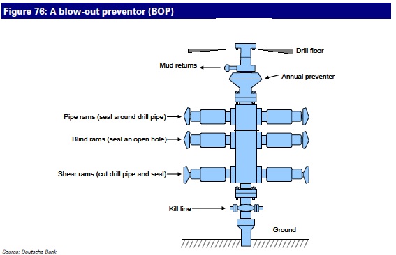
BOP stands for blow-out-preventor and is a large set of valves that sit on top of the well being drilled. The BOP will if required, seal the well quickly even if there is a drill pipe in the way. It has several sets of seals (called ‘rams’), as shown in the following figure, which are used in different circumstances.
Pipe rams to control a kick. In the case of the mud system failing to control the pressure of a reservoir, this reservoir will force fluid (oil, gas or water) into the well bore which will in turn displace mud out of the top of the well. The driller and mud engineers will see this (it is known as a ‘kick’) and try to regain control by quickly adding heavier mud into the borehole. However if no ready supply of heavy mud is available, it may be necessary to close the pipe rams – these are large rubber seals that will form around the drill pipe and seal in the kicking well. This buys time for the mud engineer to make up heavier mud, which when ready, is pumped down the center of the drill-pipe to ‘kill’ the well.
Shear rams in the last resort. If following a kick the mud weight is not raised quickly enough, or if the pipe rams leak, the reservoir fluids will continue to enter the well bore. This will decrease the aggregate well bore fluid density, and thus its weight and hence a vicious circle is setup which can quickly (within minutes in some cases) spiral into a blow-out. A blow-out initially usually takes the form of a geyser of mud shooting into the drilling rig, but if left unchecked the geyser will become increasingly full of the oil or gas from the uncontrolled reservoir. Depending on the wind conditions, this oil and gas needs only one spark to ignite it and then death and destruction are a real possibility. To avoid this unpleasant scenario the BOP contains a set of ‘shear rams’, which will cut straight through the drill-pipe and seal the well off.
Another risk with kicks is that gas can contain H2S (or ‘sour gas’), and this is not friendly stuff. It smells like rotten eggs in concentrations of 5ppm, but quickly destroys one’s sense of smell (so people think it has gone away), with inhalation proving fatal at around 20ppm.


